
AORTER CORE
Operator · Setup · Safety · Care · Warranty Guide
Updated October 2026 · 1-Year Limited Warranty
Support + Warranty · EXO@AorteFitness.com · +1 519 381 3099 · AorteFitness.com
Read, authorize, then operate

 OCCUPATIONAL AUTHORIZATION REQUIREDBefore industrial, landscaping, commercial or other occupational use, the assigned wearer must read this manual, complete fitting/training and sign the acknowledgement record. Controlled demonstrations may be performed only under direct supervision of an AORTER-qualified representative.
ONE USERONE AORTER · ONE ASSIGNED USER
ONE USERAORTER CORE is individually configured to one wearer. Cord length, tether fit and operating range depend on that person. Do not share or transfer a configured occupational unit between users.
In this manual
Configuration, capacity + warranty compliance
Safety symbols
SAFETY SYMBOLS
Know these symbols before fitting, servicing or operating AORTER CORE. Signal words indicate different levels of risk and required action.
CAUTIONPotential for minor/moderate injury or an important safe-use condition. Read and correct before continuing. WARNINGPotential for serious injury if the instruction is ignored.
 DANGERImmediate or severe hazard. Do not proceed until the hazard is removed.MOVING / RETRACTING CORDKeep hands, hair and loose material clear of the moving cord path.
 MECHANICAL INJURYKeep hands out of moving mechanisms.
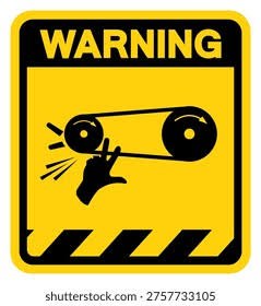
 PINCH / PULLEY HAZARDKeep fingers clear of pulleys, hinges, linears and moving interfaces.
 EYE PROTECTION / PPESafety glasses should be worn for operational use unless an approved task assessment directs otherwise. Follow site PPE rules.
COMPONENT GLOSSARY
 Carabiner / connectorApproved attachment hardware only. Style may vary.
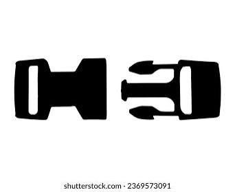 Harness clipsUsed on chest, leg or modular harness interfaces. Size/style may vary.
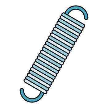 Spring setStored mechanical energy. Spring type/tension level may vary by configuration.
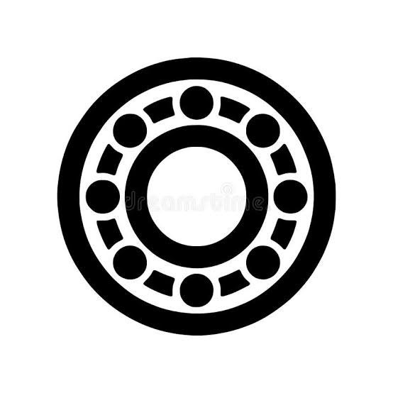 BearingInspect for smooth movement and wear. Size, mechanical type and efficiency may vary.
Rectangular sliding webbing adjuster used to change strap length.
Triangular metal hardware used for approved connector attachment. It is not a tri-clip.
Modular pulley/adjustment interface between cord and hand tether.
Protective cover removed only for prescribed cord service.
Preserve the issued AORTER configuration
Apply this rule throughout fitting, operation, inspection, maintenance and service. Where a component-specific procedure appears later in this manual, the approved-component requirement remains in effect.
From the box to first fitting
Inspect delivery condition. Check cords, cord ends, tethers, chest clips, webbing, stitching, connectors, pulleys, bearings, linear rails, springs, covers and chassis.ONE USERAssign one wearer. Begin individual cord and tether fitting. Multiple donning attempts may be required.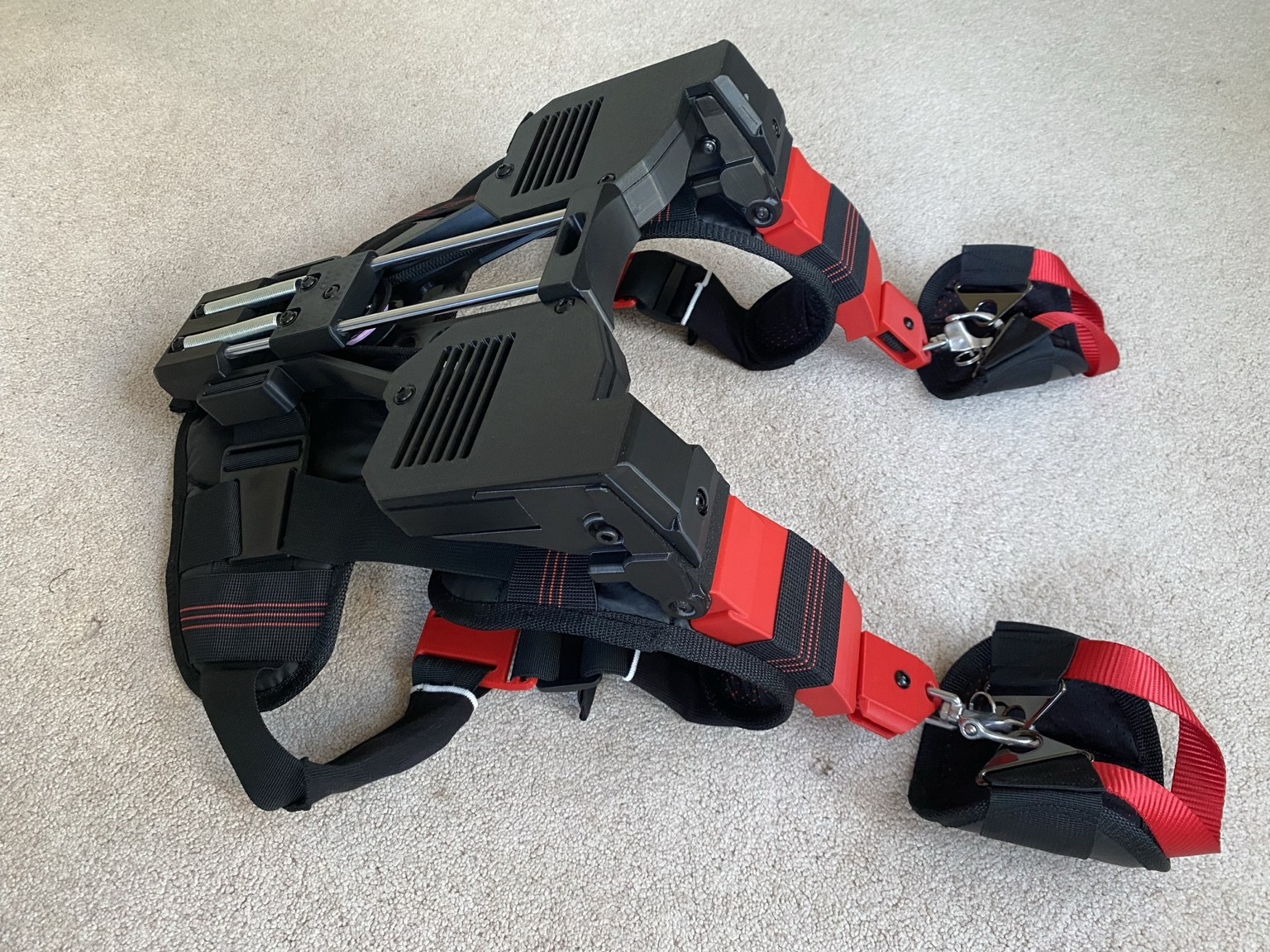
Rear mechanism + delivery confirmation
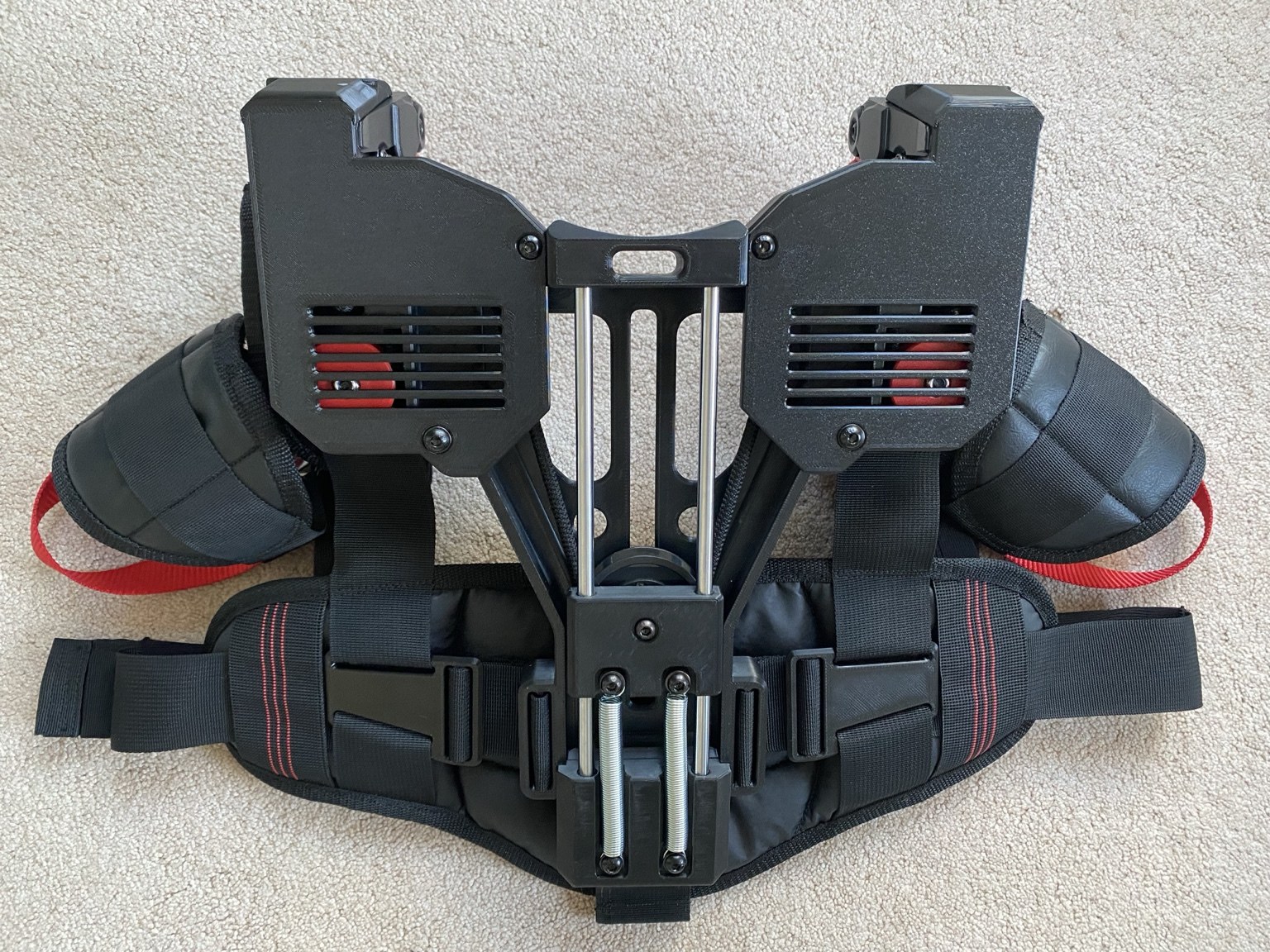 Rear mechanism view. Confirm covers, guide rails, cord pathways and visible hardware are intact before the first fitting. Do not reach into the mechanism or attempt service during this delivery check.No visible mechanical damageBoth chest clips intact
Tri-clip + strap adjustment
TRI-CLIPATTACHMENT EYEA Tri-Clip (T-Clip) is a rectangular sliding webbing adjuster. On AORTER CORE it may be black or red depending on the issued harness or modular interface. It changes effective strap length by allowing webbing to be fed through the rectangular adjuster. The triangular metal hardware at the hand/arm interface is not a tri-clip. It is a fixed attachment eye for an approved carabiner or clasp and is not used to adjust strap length.
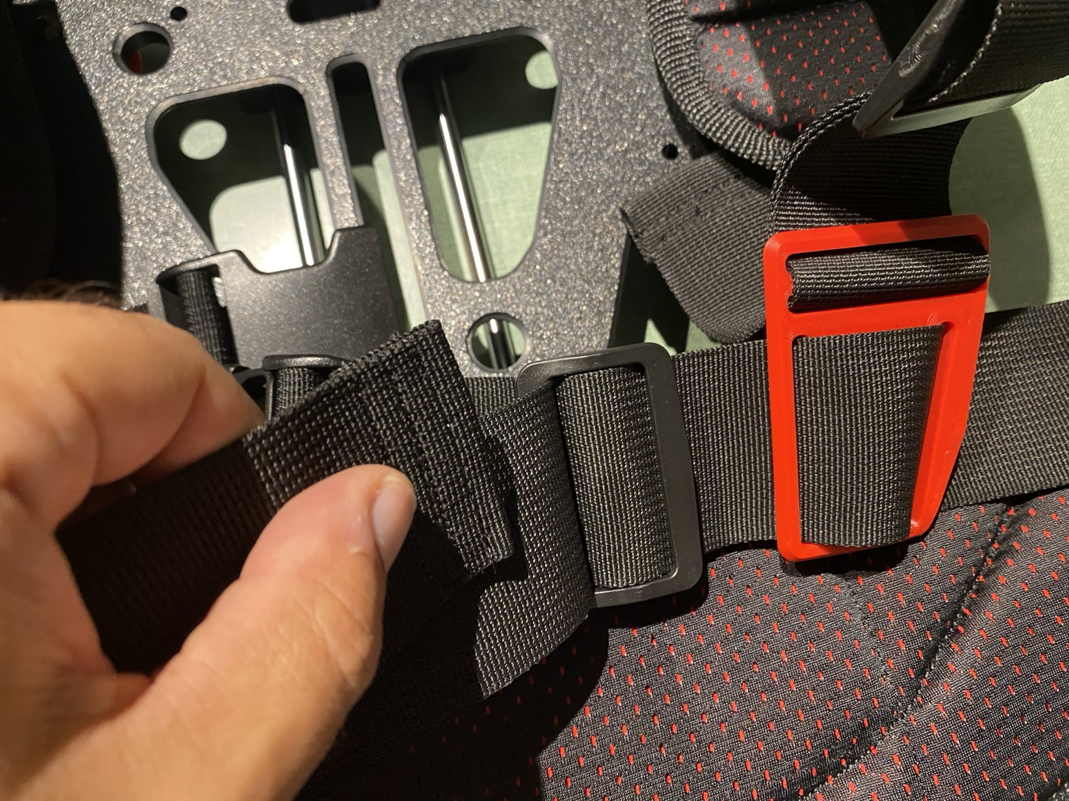 DO NOT CONFUSE THE ATTACHMENT EYE WITH A TRI-CLIPThe triangular metal eye on the hand/arm interface is connection hardware only. Do not use it as an adjustment device and do not place it in the tri-clip adjustment procedure.
Before adjustment
Support the unit, remove any operational load, and confirm the cord is secured in its designated chassis path. Make body-fit adjustments before connecting a tool or applying working tension. Inspect the adjuster and webbing for cracks, deformation, cuts, abrasion, pulled stitching, heat damage or slipping.
Feed, tighten + verify the webbing
Set the fit, then secure the excess webbing. Remove unnecessary slack without restricting breathing, circulation or normal movement. Retain excess webbing so it cannot reach cords, pulleys, tools or surrounding equipment.Verify unloaded. Don the unit and close both mandatory chest clips. While unloaded, take a full breath in and out, move the shoulders and torso naturally, and move through the intended task range. The fit must remain snug without restricting breathing, circulation or normal muscular movement. If the harness migrates, binds or changes position, stop and readjust before use.ADJUST ONLY UNLOADEDKeep fingertips out of the slot while webbing is moving. Never pull webbing through a loaded adjuster. A cracked, bent, slipping or damaged tri-clip is a stop-use condition.Dual / Quad setup + cord path
Insert unobstructed shoulder-pulley photograph and numbered continuous-cord routing diagram here. Do not use the shielded reference as the final threading instruction.
DUAL — ADJUSTABLE
One working cord per side. Used where greater adjustability and available cord travel are required. Follow the marked routing for the specific production model.
QUAD — FULL CENTRAL PATH
Two working cord runs per side. The left and right pathways mirror one another through the central pulley system and designated shoulder channels.
CORD PATH MUST BE CONFIRMED END TO ENDDo not skip a designated pulley, cross opposing sections of the continuous cord, reverse a block or substitute an unapproved channel. The cord must remain seated in each designated pulley groove and guide.Retention may vary by model. Production units may use a knot, tethered retention method, mechanical lock or later AORTER-approved locking module. Follow the markings and instructions supplied with the specific unit.
Configure the cord to the assigned wearer
ONE USERThe supplied cord may include additional length for fitting. Final cord length is determined by the assigned wearer's arm length, selected cord type, Dual/Quad routing and required movement envelope. Do not copy another person's cord length.
Establish fit before final retention
Commission unloaded. Cycle the completed configuration 20–30 times without operational load, then inspect retention, cord seating and pulley tracking again.DO NOT RECONFIGURE WHILE WORN, LOADED OR UNDER TENSIONDo not reach behind the unit to change settings. Do not allow another person to alter cord routing, knots, locks, tethers or settings while the unit is being operated.NEW APPROVED CORD REQUIRED WHEN CONFIGURATION IS CHANGEDDo not reuse a cord that has already been cut, fitted, knotted or operated in a different configuration. Only approved AORTER cords may be used.Quad shoulder position
Where the Quad configuration uses the shoulder clip/block position, keep it seated flush along the shoulder at the prescribed tightness. A loose or displaced configuration can change pulley tension and cord tracking and must be corrected before use.
Quad — Full requires guided fitting
Inspect + confirm before operational use
Inspection is not a glance at the harness. Confirm body fit, movement, cord travel and the visible mechanical system before introducing a tool or load.
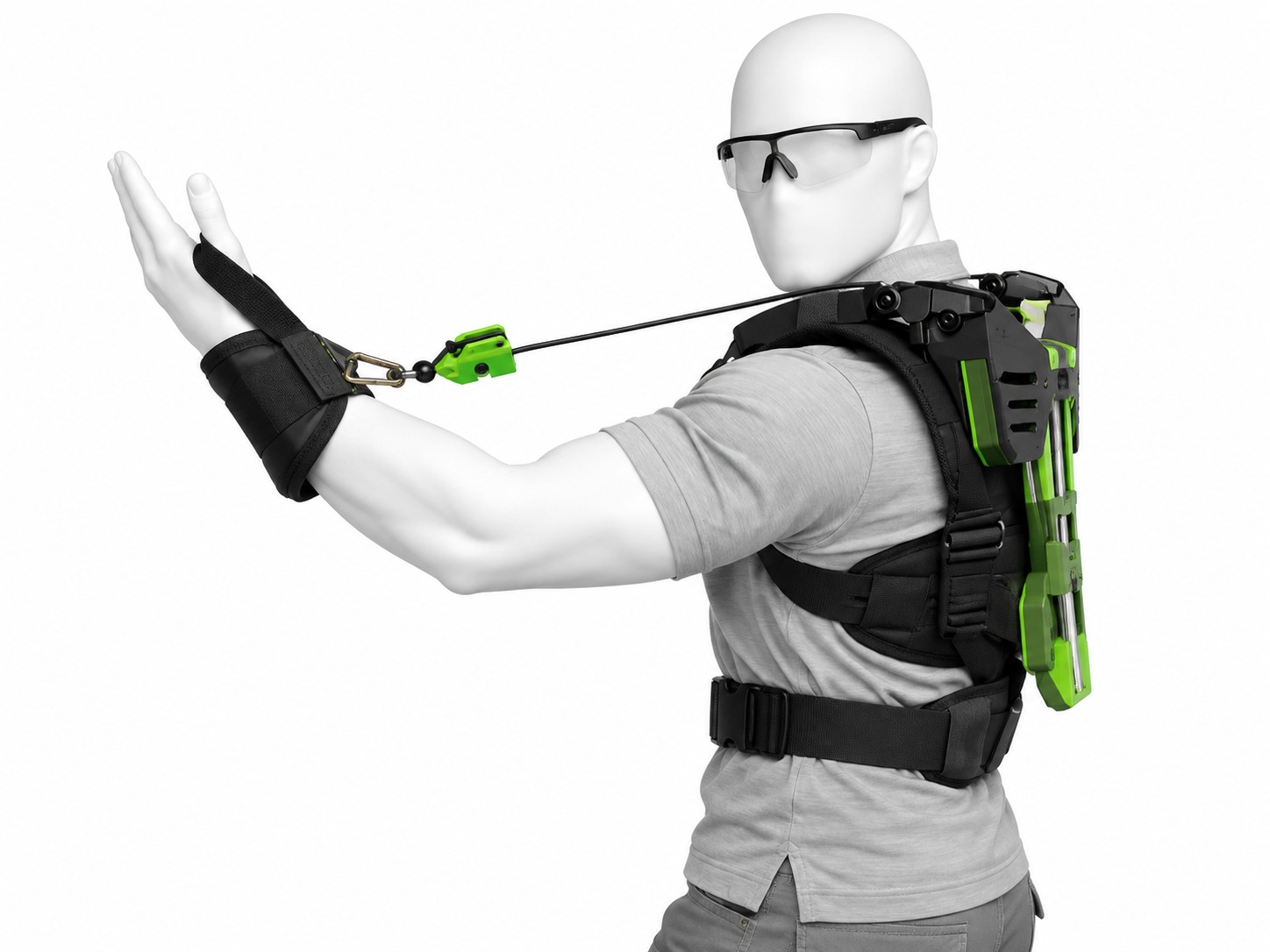 UPPER-BODY FIT. Confirm the exoskeleton is worn snugly against the body, both chest clips are closed, shoulder structures are seated, and the harness does not tip, tilt or rock during normal unloaded movement. Secure loose webbing and confirm clothing does not enter the mechanical pathway.
Move through the intended range unloaded
Use slow, deliberate movement. The wearer should be able to steer the arms naturally without a hard cord stop, strap migration, binding, unexpected recoil or interference with breathing, balance or circulation. Stop and correct any abnormal response before continuing.
Front fit + cord-reach check — Dual mode
 FRONT / SIDE MOBILITY CHECK. Confirm the connected cord length reaches the wearer’s normal grasp and working level throughout the intended movement. Set the intended tension level and verify smooth cord travel with no snagging, hard stop, strap migration or interference with clothing. The wearer must retain natural steering and control.
Rear fit + cord-travel check — Dual mode
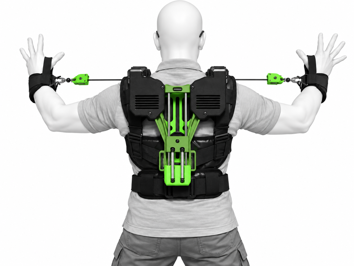 REAR FIT + CORD-TRAVEL CHECK. Confirm the harness and rear chassis sit snugly against the body without tipping, tilting or rocking as the wearer moves. Check that visible cords remain in their intended pulley path and do not snag clothing, loose webbing or other material.Clear cord pathwayWatch the visible cord path while the wearer moves. Cord travel should be smooth and deliberate, without crossing, edge contact, clothing interference or an abrupt hard stop.Body clearanceSecure long hair, loose clothing, beards capable of reaching the mechanism, jewellery, lanyards, drawstrings and loose strap/webbing ends so they cannot enter a pulley, guide, spring, rail or moving cord path.
Mechanical + body-interface checklist
Cord + retentionTrace the visible cord end to end. Look for cuts, fraying, glazing, flattening, displaced knots/locks, abnormal stretch or rubbing. Where a knot is specified, confirm it remains firmly seated with at least 10 mm (1 cm) tail.ATTACHMENT EYEConnectors + hand interfacesConfirm approved connector latches close completely, swivels move normally, attachment eyes are not bent or cracked, and hand padding/webbing is secure without restricting circulation.TRI-CLIPHarness + body interfacesInspect both mandatory chest clips, stitching, rectangular tri-clips, strap routing and any fitted leg/waist interfaces. No excess webbing may enter the mechanical pathway or nearby equipment.Rear mechanismCheck covers, pulleys, bearings, linear guide path, spring set and accessible fasteners externally. Look for binding, displaced parts, abnormal noise, corrosion, damage or unexpected recoil. Do not reach into the mechanism.ANY SIGN OF MECHANICAL WEAR, DAMAGE OR UNCERTAIN ROUTING = DO NOT USERemove the unit from service until the condition is corrected and the complete unloaded check passes again.Putting on AORTER CORE
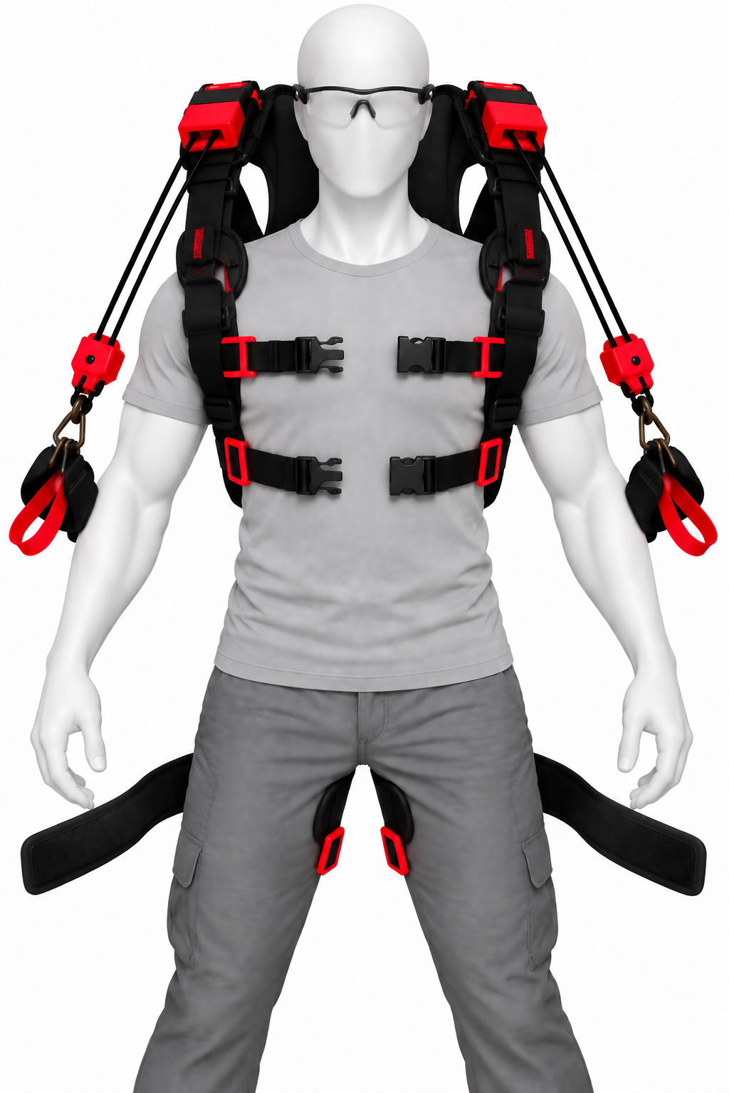
.png) 2 · Settle with chest clips open. Allow the shoulder structure and harness to sit naturally on the torso before fastening. This is a donning position only; do not operate.
2 · Settle with chest clips open. Allow the shoulder structure and harness to sit naturally on the torso before fastening. This is a donning position only; do not operate.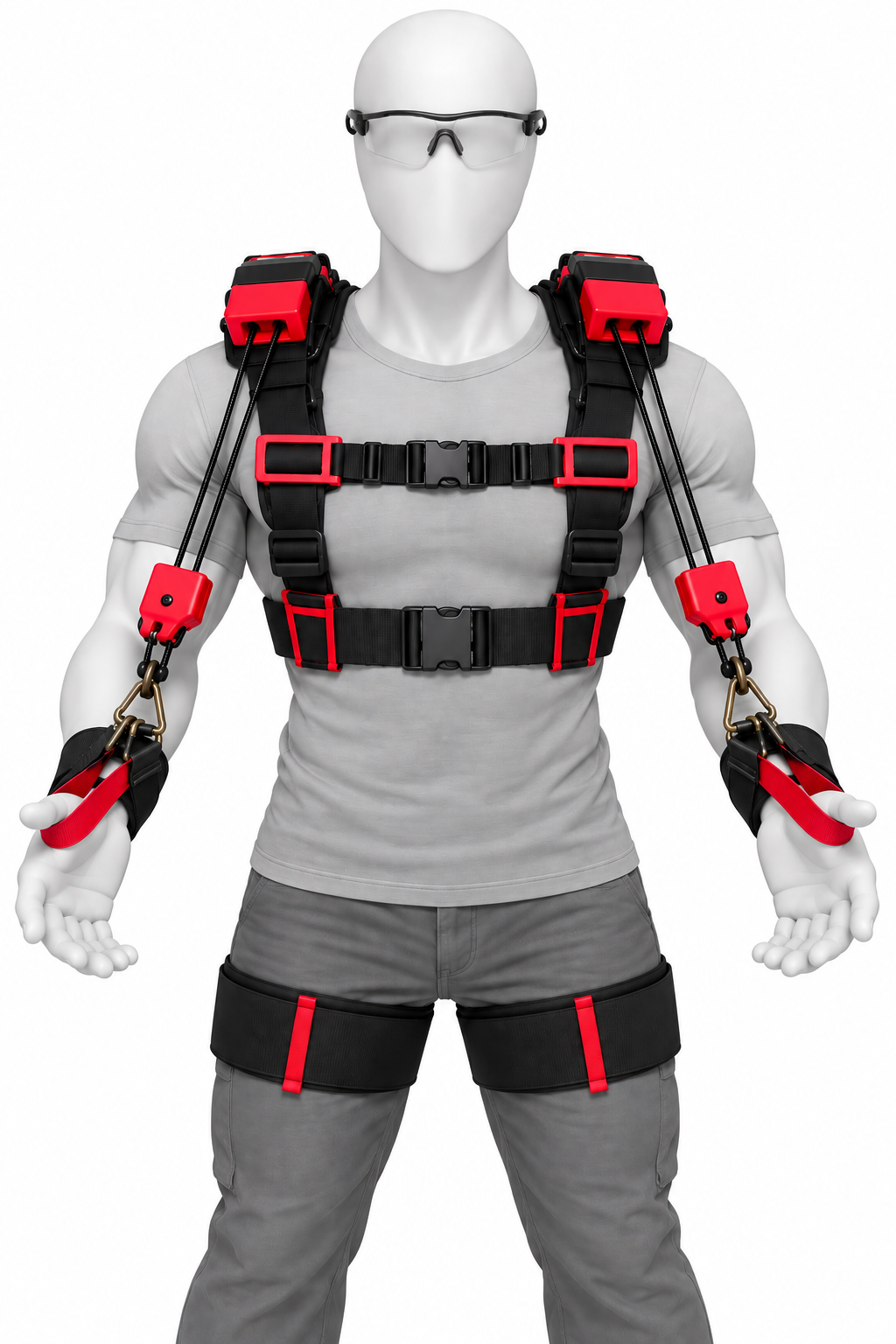 3 · Buckle both chest clips. Confirm upper and lower clips are fully closed.⚠ PLEASE BUCKLE BOTH CHEST CLIPSDO NOT USE AORTER unless both chest clips are fully buckled and secure. Both chest clips are mandatory for every configuration and every task.
Fit before connection
Allow the shoulder structure and chassis to settle before tightening body interfaces. Chest straps should stabilize the unit without restricting normal breathing or circulation. Secure all loose strap tails.
Fit and connect the hand interfaces

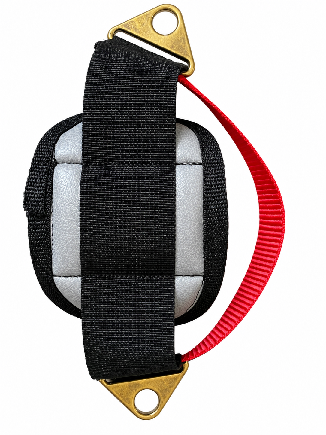 Back-side reference. Confirm webbing and attachment hardware are seated.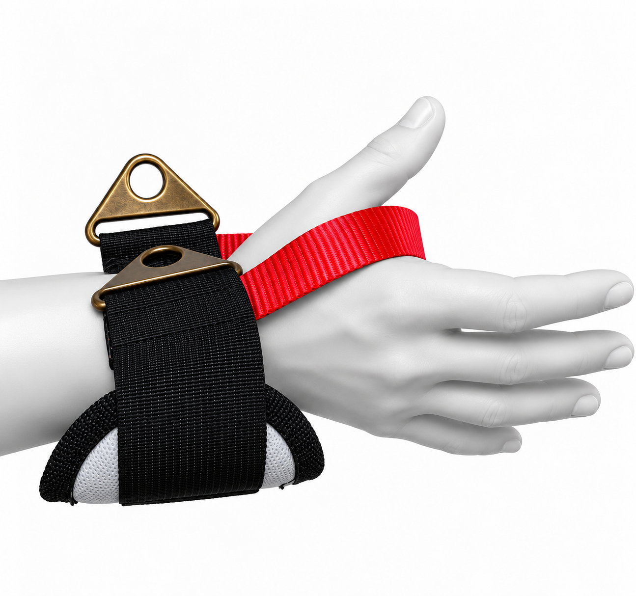
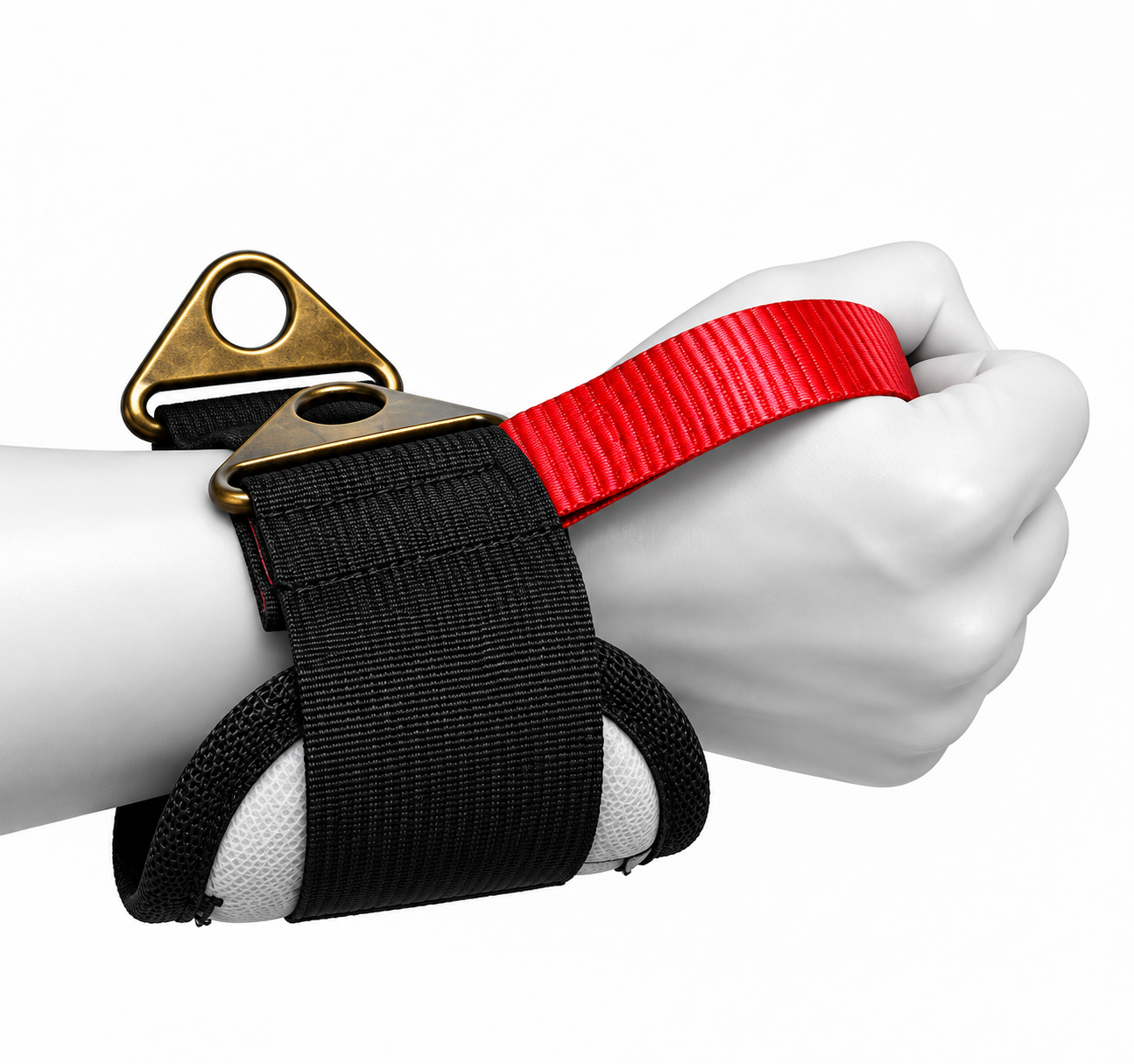
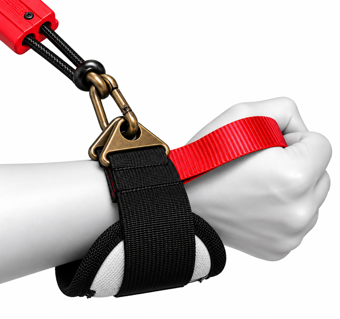 ATTACHMENT EYE3 · Connect. Attach the approved carabiner/connector to the designated attachment eye.APPROVED CORDS + ATTACHMENTS ONLYUse only AORTER-approved cords, hand interfaces, connectors/carabiners, handles, ratchet attachments and attachment hardware. Do not open a connector while it is carrying tension.
Authorized, capable users only
ONE USERONE UNIT · ONE ASSIGNED WEARER
ONE USERAORTER CORE is individually fitted. Cord length, tether settings and movement range depend on the assigned wearer. Do not switch a configured occupational unit between people.
TRAINED USERCAPABLE + TRAINED USER
TRAINED USEROnly trained users who can understand the manual, inspect the unit, control the intended tool/load, recognize stop-use conditions and remove the system safely may operate AORTER independently.
AORTER DOES NOT OVERRIDE A MEDICAL OR WORK RESTRICTIONIf a physician, rehabilitation professional, workers' compensation restriction, employer or authorized management team limits you to a particular load, movement or activity, AORTER does not increase that permitted limit. Example: a 10 lb restriction does not become 20 lb because the device provides assistance.Physical capacity
Do not use AORTER to compensate for an inability to safely perform the underlying task. If use conflicts with your medical capacity, rehabilitation plan or authorized work restrictions, do not operate unless the appropriate medical/workplace authority has approved the activity.
Impairment
Do not operate while impaired by alcohol, cannabis, recreational drugs, medication, fatigue, dizziness or any condition that reduces judgement, coordination, balance or safe tool control.
WORKPLACE INTEGRATIONMake sure AORTER is included in the organization's task assessment, PPE program, training and supervision requirements. AORTER does not replace guards, PPE, safe lifting rules or tool-specific instruction.Working with AORTER CORE
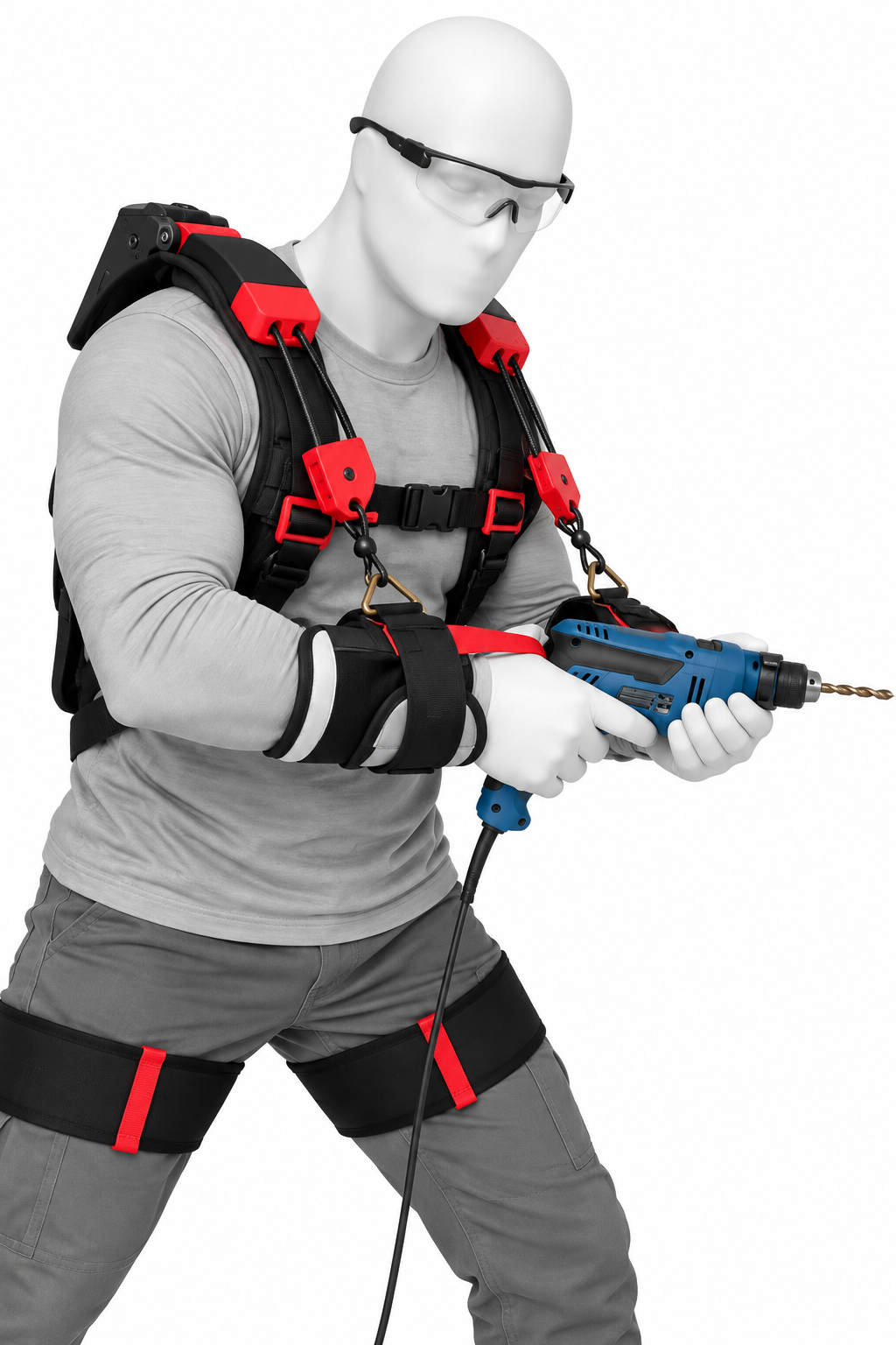
Support the movement. Do not surrender control to the system.
Move the tool through the task using normal deliberate body and arm control. Allow the AORTER to share holding demand through the configured movement pathway while the wearer continues to guide position, direction and speed. Do not hang passively from the unit, allow a tool to swing from the tether, or treat assistance as permission to use a tool that cannot be controlled safely without it.
Fluid control through the working range
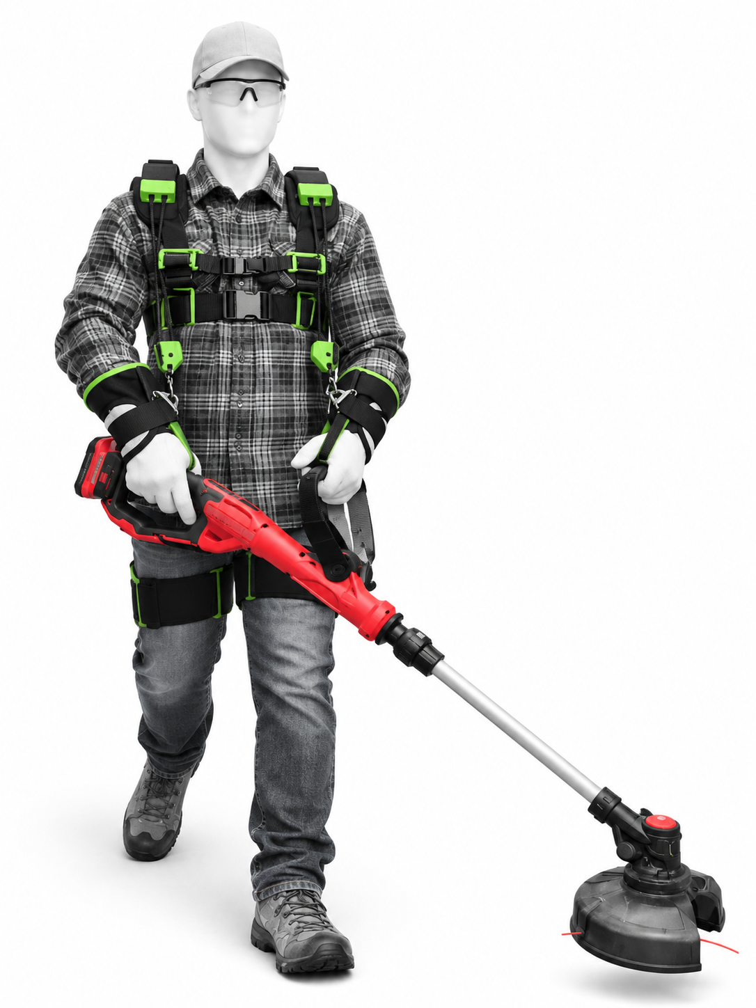
Lift, reposition + lower under control
When raising or repositioning a supported tool, establish a secure grip first, move within the configured cord range and keep the tool under positive control through the entire path. When lowering, continue to support and steer the tool rather than relying on cord tension to catch or suspend it.
If the task requires the AORTER to hold a tool that the operator cannot safely stabilize, steer, stop or remove without assistance, the task must remain within the documented maintenance, configuration and workplace safety limits for that issued unit. Reassess the tool mass, attachment method, cord configuration, wearer capability, environment and emergency removal method before continuing.
ASSISTANCE IS NOT LIFTING CAPACITYAORTER does not convert an unsafe load into a safe load and does not override medical restrictions, employer limits, tool instructions or workplace lifting requirements.Lower working position + squat verification
AORTER must remain controlled through the entire movement pathway, not only while standing. Verify the exact movement pattern expected for the task before operational loading. Assistance must never be used to force the body past a comfortable, medically permitted or workplace-authorized range.
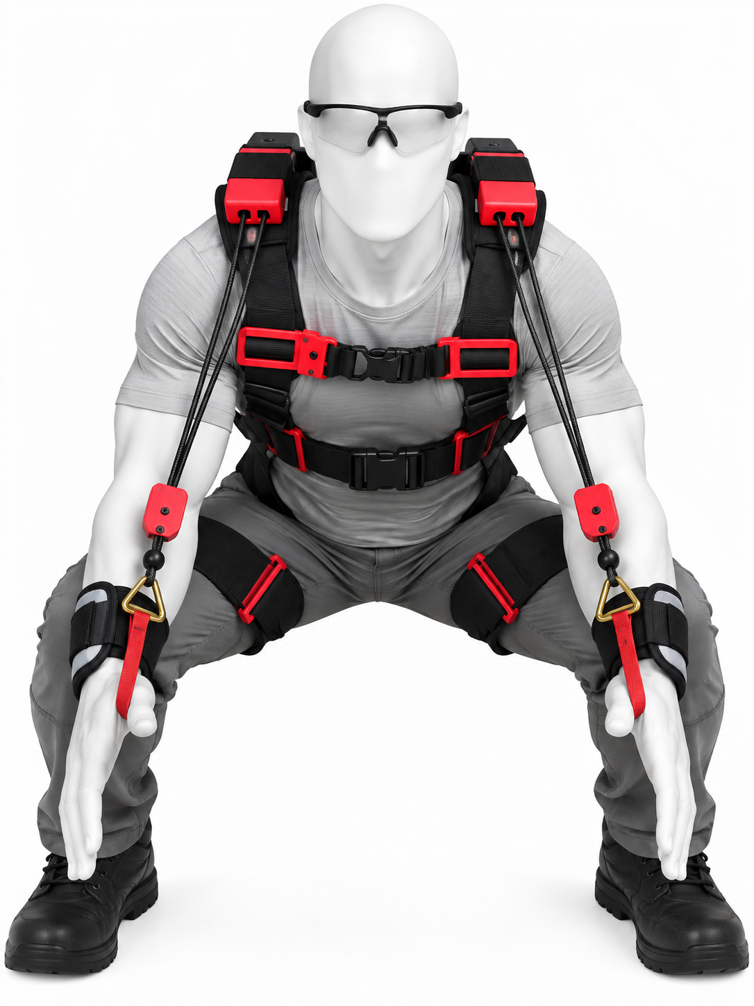
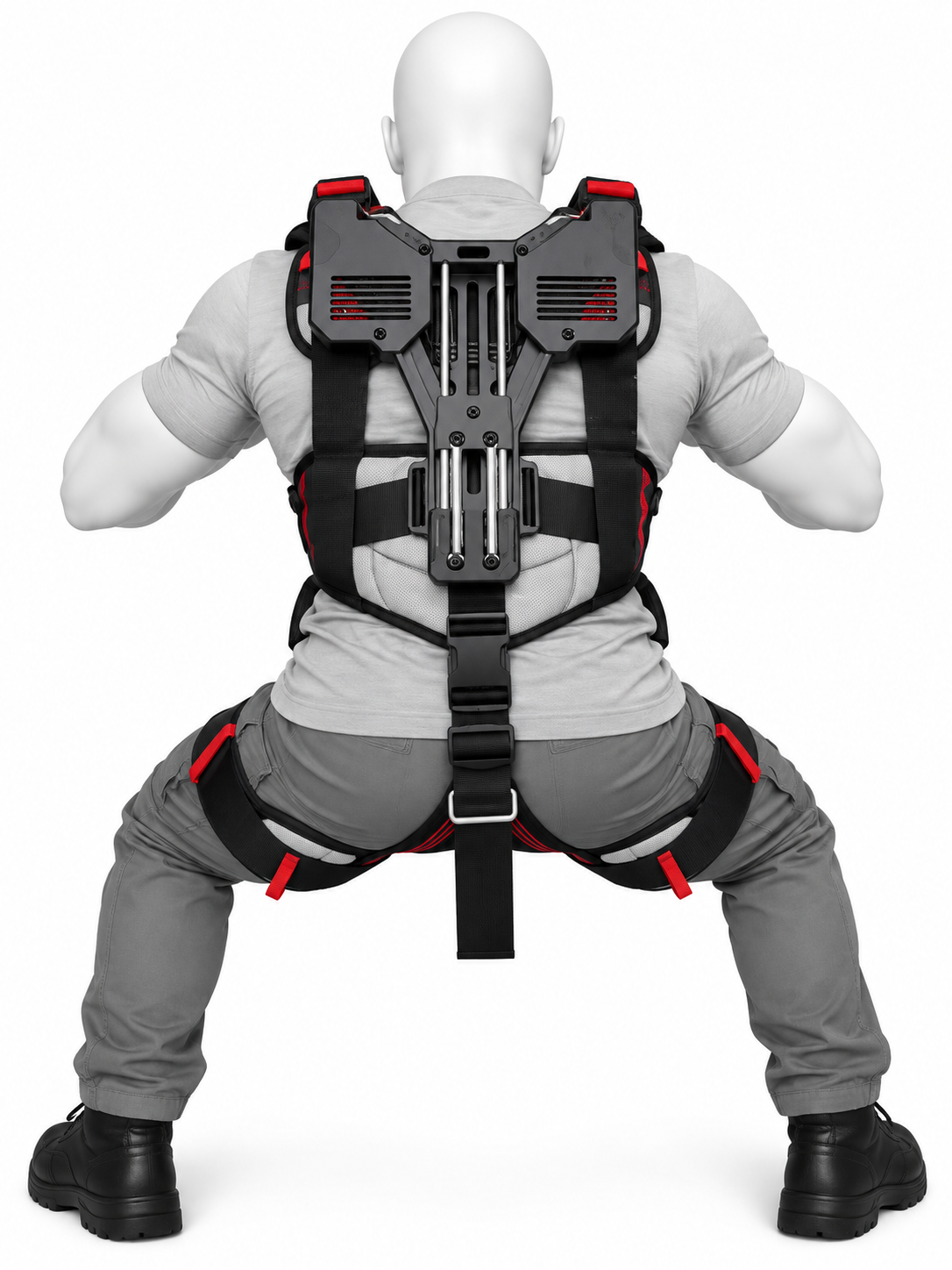 REAR SQUAT CHECK. Confirm the harness remains snug and the lower-body interfaces do not migrate, bind, twist or interfere with the rear mechanism.
Control principles
Carry, reposition + upper-body steering
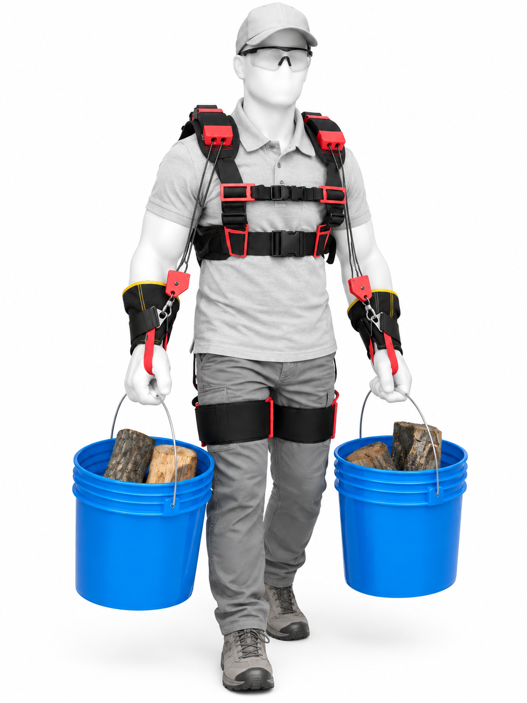
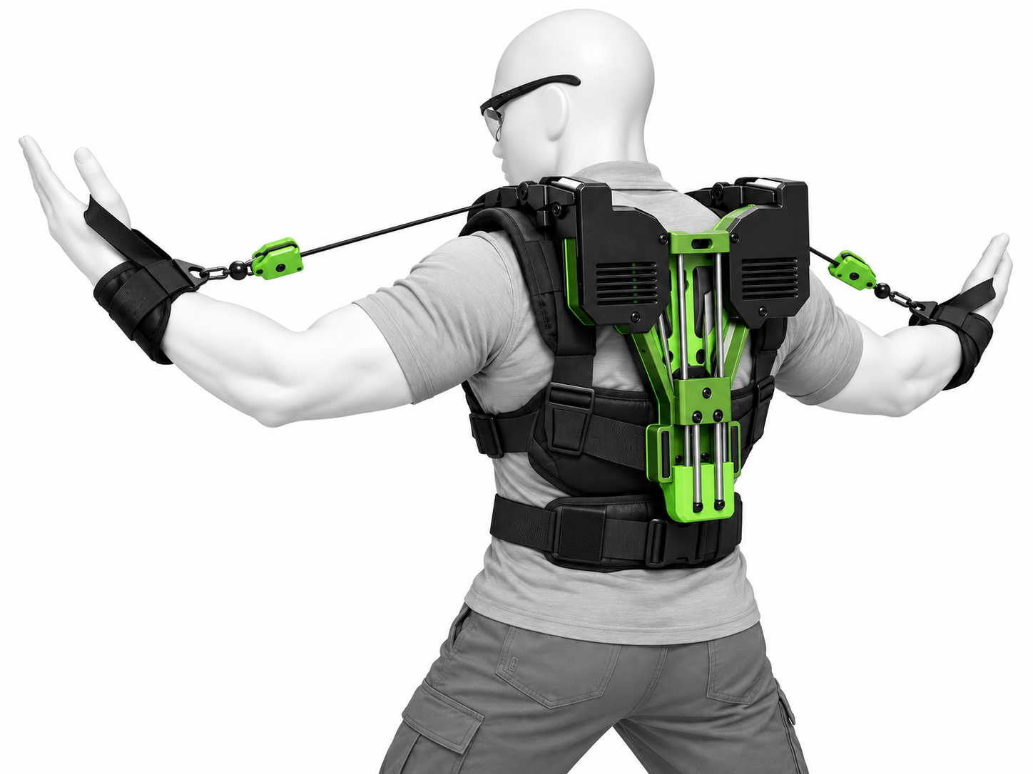 UPPER MOBILITY CHECK. Confirm bilateral cord travel remains smooth as the arms steer, reach and reposition through the intended working envelope.
Leg attachment system · full configuration
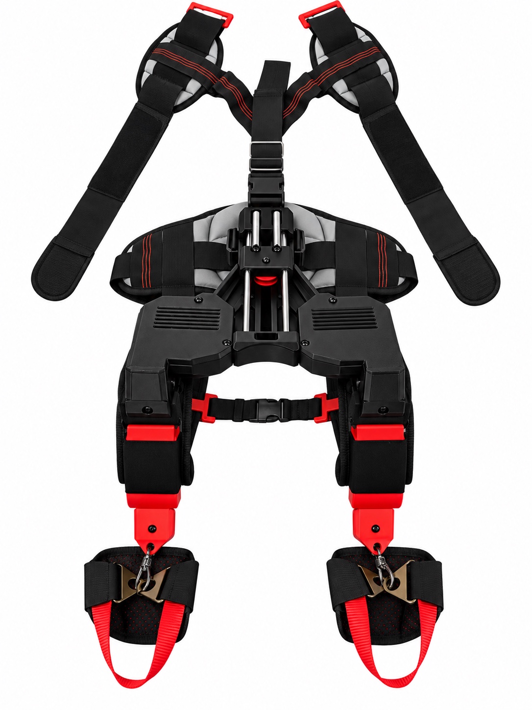 FULL LEG-ATTACHMENT CONFIGURATION. Use this full-system reference to identify the relationship between the CORE chassis, bilateral leg attachment modules, attachment hardware and body-support webbing. This is a component/configuration reference, not a donning photograph.
ATTACHMENT EYEBefore fitting, confirm the correct modular components are present for the issued configuration. Inspect webbing, stitching, rectangular adjusters, clasps, attachment eyes and connection hardware. No module should be improvised from unrelated harness parts.
ONE ASSIGNED WEARER · VERIFY UNLOADEDLower-body support is individually fitted. It does not increase a medical, workplace or tool lifting limit and does not authorize a task the wearer could not otherwise perform safely.Leg module · clips open
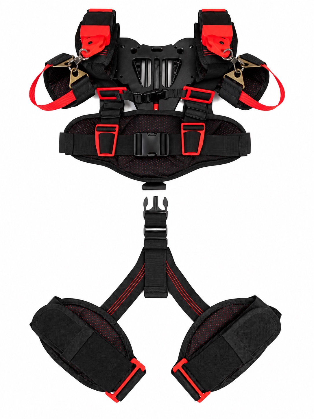
Connect or disconnect only while the system is unloaded and controlled. Keep fingers clear of clasp and buckle pinch points. Do not connect a partial latch, damaged clasp or twisted webbing.
ONE ASSIGNED WEARER · VERIFY UNLOADEDLower-body support is individually fitted. It does not increase a medical, workplace or tool lifting limit and does not authorize a task the wearer could not otherwise perform safely.Leg module · clips connected
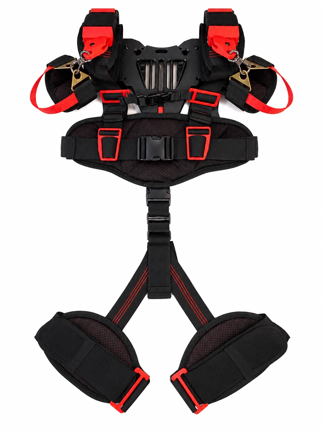
TRI-CLIPONE USERAfter connection, adjust the rectangular tri-clips/webbing adjusters as required for the assigned wearer. Secure loose tails. The leg pads should remain positioned through the intended movement range without cutting into the wearer, rotating excessively or pulling the chassis out of alignment.
ONE ASSIGNED WEARER · VERIFY UNLOADEDLower-body support is individually fitted. It does not increase a medical, workplace or tool lifting limit and does not authorize a task the wearer could not otherwise perform safely.Rear mechanical + leg relationship
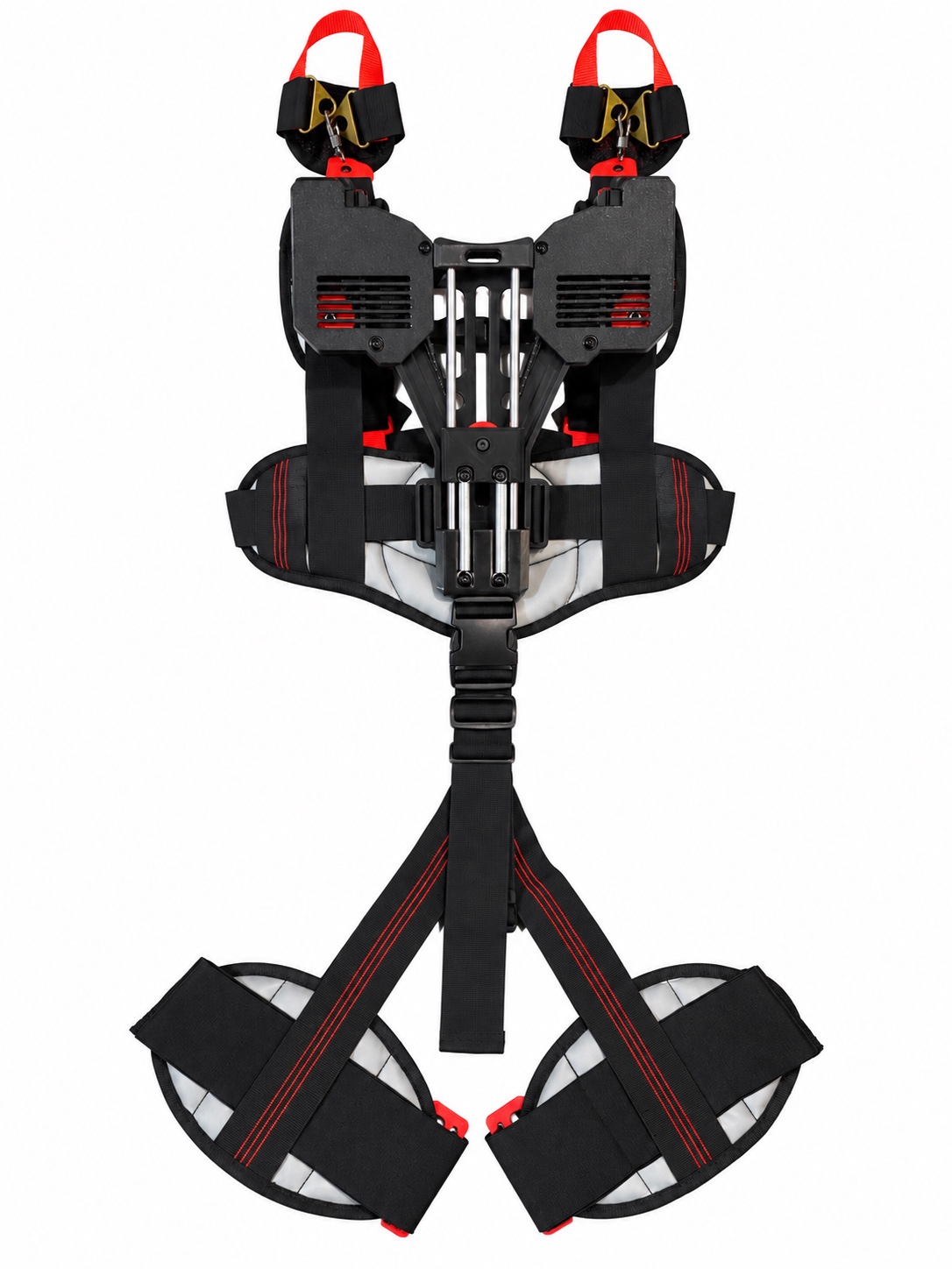 REAR FULL-SYSTEM REFERENCE. Use this rear view to verify how the lower-body module relates to the chassis and bilateral mechanical system.
With the unit fitted, perform the prescribed unloaded movement verification. Confirm the leg interfaces remain secure through standing, walking and the intended lower working range. The squat photograph belongs to the Movement Range section only and is not used here as a leg-module reference.
ONE ASSIGNED WEARER · VERIFY UNLOADEDLower-body support is individually fitted. It does not increase a medical, workplace or tool lifting limit and does not authorize a task the wearer could not otherwise perform safely.Extra-secure requirements
⚠ DRAW-IN HAZARDKeep cord, webbing, clothing and hair controlled around equipment capable of pulling material inward.⚠ MECHANICAL HAZARDKeep hands and loose material away from moving machinery and AORTER mechanisms.⚠ PINCH HAZARDNever reach into pulleys, shafts, belts, rollers, gears or other moving interfaces.Equipment capable of pulling or capturing material
For drill presses, belt sanders, lathes, rollers, conveyors, shafts, spindles, chucks and similar draw-in equipment, perform an additional task-specific safety check before use. Secure hair, clothing, every strap tail and every AORTER interface.
QUAD MODE REQUIRED FOR THIS CLASS OF APPROVED APPLICATIONDual / adjustable mode must not be used where its available adjustment cord could create an additional snag hazard. Quad mode does not remove the inherent hazards of the machine. All guards, workplace controls and tool-specific safety procedures remain mandatory.Both chest clips buckledAll connectors closedKnow the task before tethering the tool
TRAINED USERAORTER may be used independently by a trained, authorized wearer after fitting and task verification. Additional supervision is appropriate for first use, unfamiliar tools, low-clearance work, unusual body positions, new configurations, or tasks where the rear mechanism cannot be readily observed by the wearer.
Tool competency comes first
The wearer must already understand the connected tool's controls, normal handling, guards, hazards, emergency stop procedure and required PPE. Do not learn an unfamiliar tool while simultaneously learning AORTER. Full tool suspension or higher-demand support should only be introduced after the user demonstrates stable control of the tool without relying on the exoskeleton to compensate for poor technique.
External observer
An observer may confirm rear clearance, cord tracking, strap position and interference with the environment. The observer must never place hands into the mechanism, pull a cord, open a connector, change a setting or reach behind the unit while it is worn or under tension.
THIRD-PARTY TOOL HAZARDS REMAIN THIRD-PARTY TOOL HAZARDSAORTER does not remove blade, bit, chuck, sanding, cutting, electrical, vibration, kickback, entanglement or other hazards created by the connected tool. Tool misuse is not made safe by tethering the tool to AORTER.LOW CLEARANCE / CONFINED WORKConfirm adequate clearance for the shoulder assemblies, rear chassis, cords and modular tethers before entering the work area. If contact with surrounding structures can force, trap or snag the mechanism, do not proceed until the task is controlled.Unload, disconnect, remove, inspect
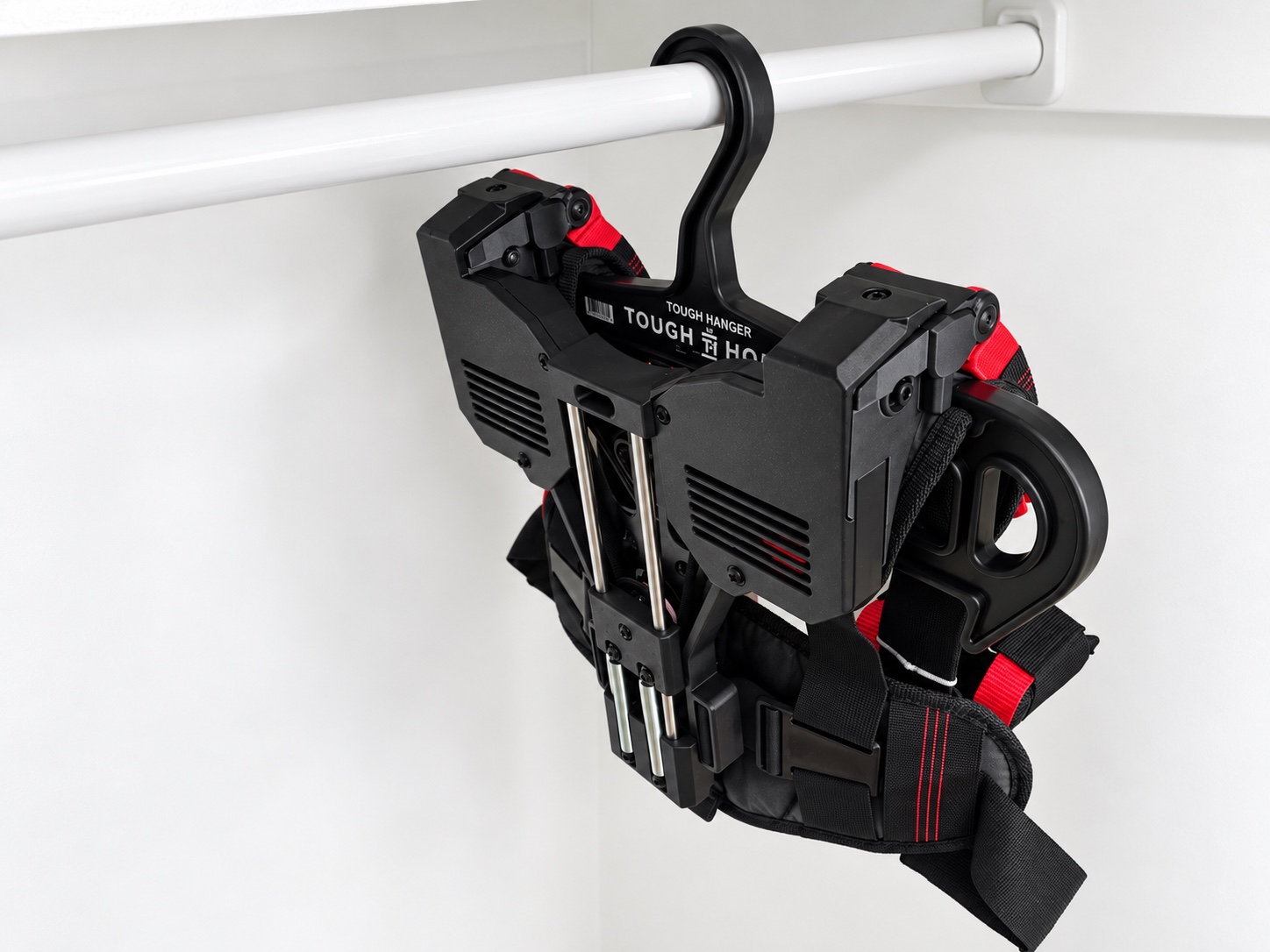 Disconnect the hand interfaces. Release the approved connector only after tension is removed.Release body interfaces. Open both chest clips and remove applicable tethers.Inspect after use. Check cords, retention points, tethers, straps, clips and visible mechanical components before storage.NEVER DISCONNECT OR SERVICE UNDER LOADDo not release a loaded connector, cord retention point or rear cover while the system is tensioned.
Configuration changes are maintenance work
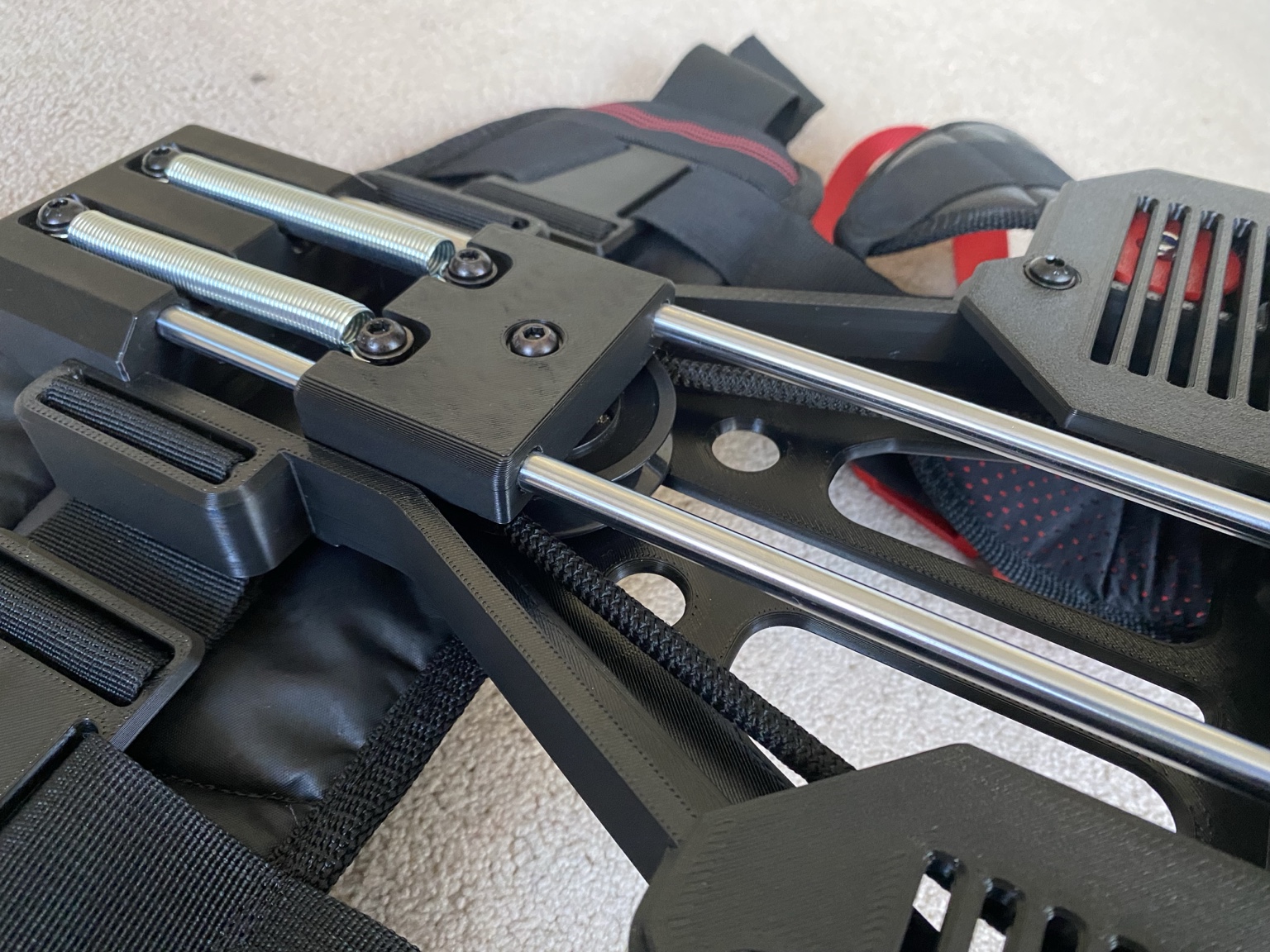 Linear block / guide reference. Keep the mechanism unloaded and fingers clear during prescribed service.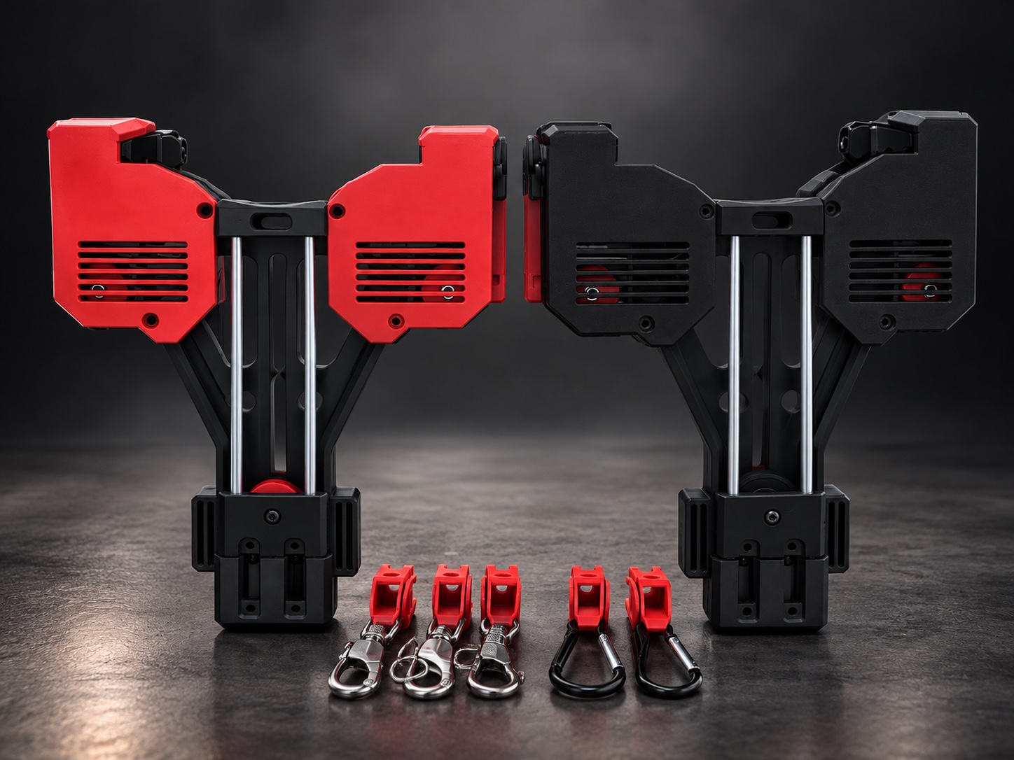
Mandatory cord-change rules
REAR CAGE / COVERRemove the unit from the wearer, unload all tension, undo/release both retention points, remove the rear cage only for the prescribed cord procedure, and install a new approved cord every time the configuration is changed. Replace the rear cage before testing or use.
Current applicable rear covers use the designated three cover bolts (1–2–3) with a 6 mm Allen key. Do not over-tighten. Later models may use different approved retention or cover hardware; follow the model markings.
COMMISSION AFTER EVERY NEW CORD / CONFIGURATIONSeat the quad clip flush at the shoulder where applicable. Secure retention points, maintain at least 10 mm (1 cm) tail beyond a finished knot where knots are used, then cycle the unloaded system 20–30 complete times. Reinspect knots/locks and cord condition before operational use.Keep the system serviceable
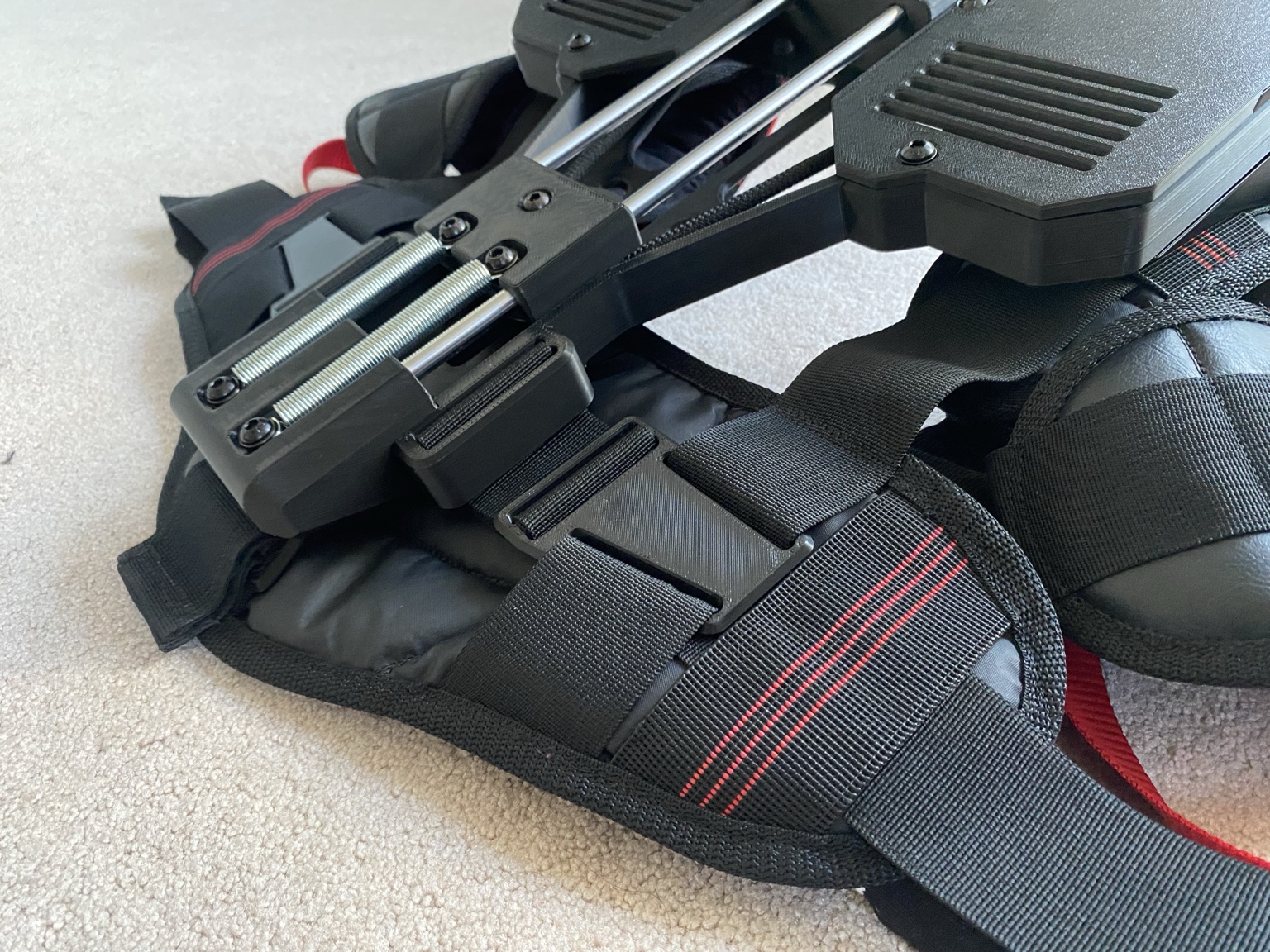 Linear block / spring set. Inspect for obstruction, wear and abnormal movement.
Reassembly after cleaning or strap removal
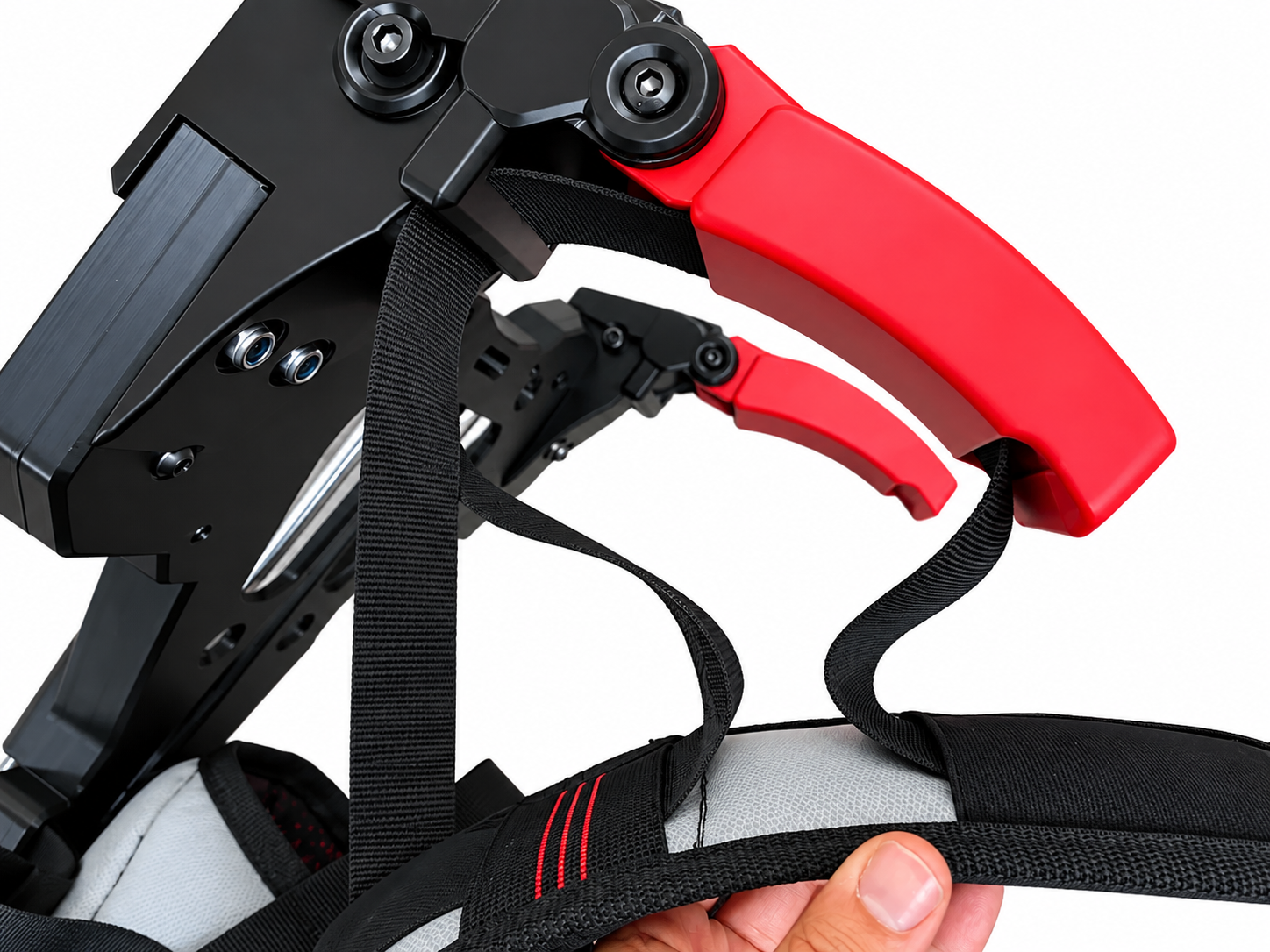
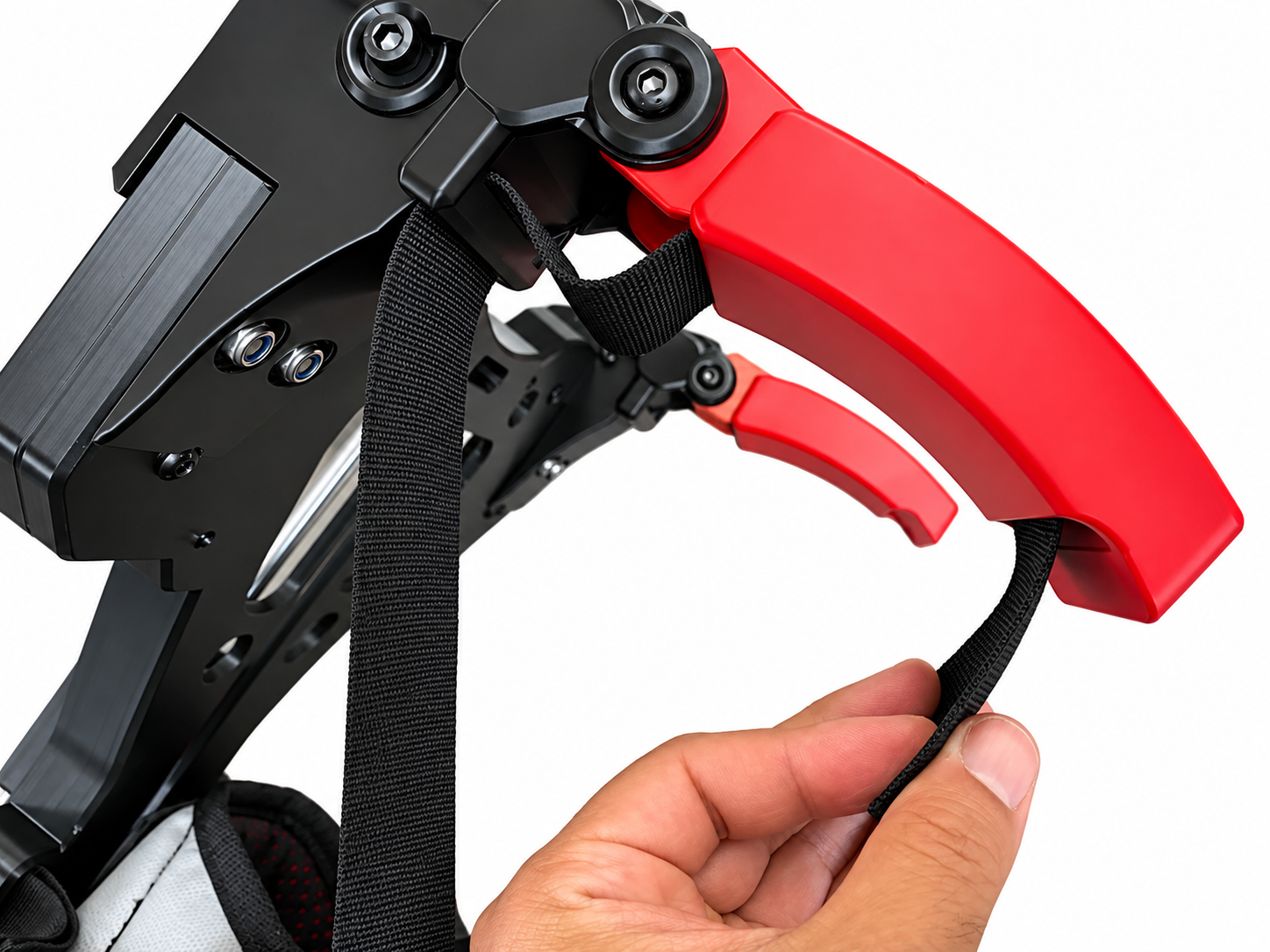
Before every use
Inspect cords, knots/retention, tethers, straps, stitching, chest clips, connectors, pulleys, bearings, linear rails, springs, covers and accessible fasteners. Stop at the first sign of fraying, knot displacement or abnormal mechanical wear.
Scheduled care
Safety glasses are required during authorized maintenance or repair where cords, springs, retracting components, covers or stored mechanical energy may be exposed. Unload the unit and remove tension before service.
Use only the lubricant and service points specified by AORTER. Service intervals for lubrication and preventive cord retirement must follow the released model-specific maintenance schedule; do not extend an interval because a cord “looks fine.”
Sharp objects
Do not allow cords, straps or tethers to contact knives, exposed blades, sharp sheet metal or cutting edges. If contact occurs, stop and inspect before reuse.
DISCOMFORT OR ABNORMAL RESPONSE = STOP USEStop for pain, numbness, tingling, circulation restriction, dizziness, abnormal resistance, unusual noise, binding or unexpected recoil. Contact AORTER or an authorized distributor for fit/service review before resuming use.Cord wear is a service condition
SAFETY GLASSES REQUIRED FOR CORD OR MECHANICAL SERVICEUnload the unit and remove stored tension before inspection or service. Wear safety glasses whenever opening a cover, handling a tensioned/retracting cord path, or performing authorized mechanical maintenance.Cord service-life rule
Cord life depends on task intensity, abrasion, contamination, routing, load cycles, environment and configuration. Inspect before every use and after demanding or abrasive work. Replace immediately at the first sign of fraying, glazing, flattening, cuts, abnormal stretch, displaced retention, heat/chemical damage or uncertain history. Install a new approved cord whenever the unit is reconfigured for a different wearer/configuration as specified in this manual.
Replacement cord source
Operator/end-user replacement cords must be the approved AORTER cord specified for the unit and hardware revision and obtained through Aorte Fitness Inc. or an authorized distribution/service channel. Do not substitute cord based only on diameter, appearance or perceived strength.
Preserve the fitted configuration
Cleaning
Clean only as permitted for the released model and materials. Remove surface dirt without forcing debris into pulleys, bearings, linear channels, springs or cord pathways. Do not use cleaning as a substitute for replacing a damaged or contaminated cord, tether or strap.
Transport + storage
Transport and store the unit unloaded. Protect it from crushing, sharp objects, uncontrolled snagging, excessive heat, chemicals, moisture and unauthorized handling. Do not place heavy objects on the shoulder assemblies, rear chassis, hand blocks or exposed cord path.
Configuration record
ONE USERFor occupational units, keep the assigned wearer, hardware revision, cord type, Dual/Quad configuration, approved attachments, fitting date, service actions and any restrictions with the unit. If the unit is removed from service, record the reason and do not return it to operation until the required inspection or authorized repair is complete.
Service/repair history retainedReturn-to-service authorization documentedONLY AUTHORIZED REPAIRDo not splice cord, substitute load-bearing fasteners, glue/reshape structural components or improvise repairs. Repairs outside the user-permitted maintenance procedures must be completed through AORTER or an authorized distribution/service channel.Know the issued material configuration
AORTER CORE uses approved material families according to configuration. Not every unit contains every material listed below. The issued configuration and controlled production record govern.
Handling + cleaning
- Inspect plastic components for cracks, chipped edges, exposed or loose fibres, distortion, layer separation and unusual wear.
- Avoid rubbing damaged or abraded fibre-filled surfaces against bare skin. Use suitable gloves when handling rough or damaged parts.
- Do not sand, drill, flame-polish, heat-reshape, solvent-smooth or coat structural components as routine operator maintenance.
- Wipe accessible plastic surfaces with a soft cloth and mild cleaning solution only where compatible with the issued materials.
- Prevent liquid and debris entering bearings, pulley mechanisms, linear channels, springs and cord pathways. Dry cleaned components before service.
- Follow the issued textile care label. Do not introduce unapproved solvents, bleach, disinfectants, oils or finishing products.
Environment, physical response + emergency readiness
Before issuing AORTER for occupational use, evaluate the wearer, task, environment, PPE, escape route and interaction with other equipment. A successful fitting does not by itself authorize every task or environment.
Heat + environmentAccount for temperature, humidity, rain/wet exposure, contamination and the added clothing/PPE required by the workplace. Stop if environmental conditions affect grip, balance, visibility, material condition or the wearer’s ability to recognize a hazard.TRAINED USERFatigue + adaptationA new wearer requires familiarization. Begin with unloaded movement and controlled task practice. Do not treat reduced perceived effort as proof that the task, load or duration is safe.Emergency removalBefore work, the wearer and supervisor must know how to support the tool/load, remove tension and release body interfaces. Emergency procedures must remain compatible with the workplace rescue plan and required PPE.Third-party PPEAORTER does not replace required PPE. Confirm compatibility with eye, head, hearing, respiratory, fall-protection and other required equipment before work. If equipment interferes with correct fit or function, do not improvise a configuration.STOP IF THE WEARER CANNOT SELF-CONTROL THE TASKIf the wearer cannot safely support, steer, stop, lower or disengage from the tool/load without depending on the exoskeleton to prevent loss of control, the task/configuration requires reassessment before use.Support does not replace task control
AORTER is a wearable support system. It must be integrated into the existing safe method of work rather than used to bypass lifting limits, machine guarding, tool instructions, job-specific procedures or medical/work restrictions.
Reassess when anything changes. A different wearer, tool, attachment, cord, Dual/Quad mode, PPE combination, work height, machine, environment or task pathway requires renewed verification.NO INCREASE TO AUTHORIZED CAPACITYAssistance does not increase a medical, employer, workers’ compensation or regulatory lifting restriction. If a wearer is restricted to 10 lb, AORTER assistance does not authorize a 20 lb task.Understand the mechanical load path
AORTER CORE is a passive mechanical support system. The production configuration uses routed cord, re-direction/control pulleys, body interfaces and mechanical resistance elements to redistribute force through the intended movement pathway. The user must remain in control of the actual tool or load.
Safe use remains a shared responsibility
User responsibility
ONE USERTRAINED USERThe assigned wearer must read and sign this manual before occupational use, complete required fitting/training, inspect before every use, use only the approved configuration and attachments, stop when conditions become unsafe, and report damage or abnormal operation immediately.
Employer / purchaser responsibility
TRAINED USERThe employer or purchaser must assess the task and environment, confirm the wearer is trained and authorized, provide required supervision and PPE, preserve machine guards and other safeguards, maintain training/service records and comply with applicable workplace requirements.
Tool responsibility
AORTER does not train a wearer to use a drill, trimmer, sander, press, grinder or other third-party tool. The wearer must already understand that tool's controls, hazards, guarding, PPE and emergency procedures. Misuse of a connected tool is not converted into safe use by tethering it to AORTER.
LIMITS OF ASSISTANCEAORTER redistributes holding demand. It does not eliminate object mass, make an unsafe load safe, increase a medical/work restriction, guarantee injury prevention, replace safe lifting technique, replace PPE or remove the inherent hazards of the connected tool or work environment.Authorized service + configuration control
Use only approved cords, attachments and service procedures. Repairs to load-bearing, cord-routing or mechanical components must be performed by AORTER or an authorized distribution/service partner. Do not splice cords, substitute hardware, drill, glue, heat, reshape or improvise repairs.
UNCERTAINTY = STOPIf instructions conflict, the configuration cannot be verified, or the safe condition of the unit is uncertain, do not operate under load. Contact AORTER or an authorized distribution/service partner.User acknowledgement + authorization
NO SIGN-OFF = NO AUTHORIZED OCCUPATIONAL USEA controlled supervised demonstration does not constitute authorization for industrial, landscaping, commercial or other occupational use.I acknowledge that I have read the current AORTER CORE manual in full, received instruction regarding fitting, inspection, operation and removal, understand the warnings and limitations, and have demonstrated the required procedures before being authorized to use this individually configured unit.
TRAINED USERTraining confirmation
Both chest clips understood as mandatorySigning this record does not permit the wearer to disregard workplace safety requirements, medical restrictions, applicable law, employer instructions, tool instructions or any warning contained in AORTER documentation.
Manual, unit and on-product warnings work together
Keep this manual available to the assigned wearer and workplace. Record the unit serial/hardware revision, configuration and assigned wearer. If a production occupational unit carries on-product warning symbols, labels or configuration marks, keep them legible and unobstructed.
Symbols supplement the manualOn-product symbols provide rapid hazard recognition. They do not replace the full instructions, task assessment, training or sign-off in this manual.AORTER CORE · 1-Year Limited Manufacturer Warranty
This warranty guide accompanies the Operator Manual. The written warranty supplied with the sale and applicable statutory rights control if there is any conflict.
Coverage period
The AORTER CORE limited manufacturer warranty is one year / 12 months from the applicable commencement date stated in the written warranty terms or sales documentation.
What the warranty is intended to address
Subject to the written terms, AORTE FITNESS INC. may review claims involving suspected defects in supplied materials, workmanship or manufacturer-provided components arising during authorized normal use. A claim is not automatically accepted because a component has worn, loosened, been damaged or reached the end of its service life.
Consumable / service items — not covered
Cords and clips/connectors are service-life items and are not covered by the one-year limited warranty for wear, fraying, abrasion, cutting, deformation, loss, contamination, impact damage, misuse or routine replacement. These parts are expected to be inspected and replaced as their condition, task exposure and configuration require.
If a cord or clip/connector is supplied damaged, incorrect or with an apparent manufacturing defect at delivery, do not use it. Report the condition to AORTE FITNESS INC. or the authorized distributor before occupational use.
Approved replacement parts are required
Operator/end-user replacement cords, clips/connectors and other load-path components must be the AORTER-approved part specified for the model and hardware revision and obtained through AORTE FITNESS INC. or an authorized distribution/service channel. Use of an unapproved substitute may affect warranty coverage and requires the unit to be removed from service until the approved configuration is restored and verified.
Warranty eligibility conditions
Maintenance/service requirements followedMANUAL REVIEW + OCCUPATIONAL SIGN-OFF ARE CONDITIONS OF AUTHORIZED OCCUPATIONAL USEAORTE FITNESS INC. may review compliance with required setup, inspection, assigned-wearer, configuration, maintenance and sign-off procedures when substantiating a warranty claim. Failure to follow required procedures may affect coverage to the extent permitted by the written warranty and applicable law.What is not automatically a manufacturing defect
Normal consumable wear, scheduled cord replacement, cosmetic wear, fit adjustments, contamination, damage from external tools/equipment, impact, cutting, abrasion, improper storage, unauthorized parts or operation contrary to this manual are reviewed separately from defects in supplied materials or workmanship.
No expansion of safe-use limits
Warranty coverage does not authorize operation outside the manual, outside the wearer's restrictions or outside approved tool/task limits.
Conditions that may affect coverage
ONE USERAORTE FITNESS INC. reserves the right to substantiate a claim before reaching a warranty determination. Review may include the physical unit, photographs, serial/hardware revision, assigned wearer record, cord type, routing, attachments, maintenance history and circumstances of the reported failure.
Examples reviewed for misuse / alteration
- Unauthorized repair, drilling, gluing, heating, reshaping or modification.
- Unapproved cord, connector, attachment, fastener or substituted hardware.
- Improper Dual/Quad routing, loose configuration or operation with an incorrectly seated quad clip.
- REAR CAGE / COVERRear cage/cover removed during operation or not correctly reinstalled after service.
- Operation after visible damage, fraying, displaced retention, abnormal noise, binding or other stop-use condition.
- Reconfiguration while worn, loaded or under tension.
Wear / environment / third-party causes
- Normal wear or consumable/service-life replacement is evaluated separately from a manufacturing defect.
- Cutting, abrasion, sharp-object contact, contamination, crushing, improper storage or transport damage.
- Damage caused by a third-party tool, machine, load, impact or work environment.
- Failure to secure hair, clothing, webbing tails or other entanglement hazards.
- Use by a person other than the assigned occupational wearer.
- TRAINED USERFailure to follow required inspection, maintenance, training or sign-off procedures.
Keep proof of purchase and the unit serial/hardware revision. Warranty rights, transferability and commencement date are governed by the written sales/warranty terms and applicable law; do not assume that reassignment of a fitted occupational unit transfers its authorization or fitted configuration.
Proof + transfer
For a defect accepted under the limited warranty, AORTE FITNESS INC. may, at its option and subject to the written warranty and applicable law, repair the covered component, replace it with an equivalent new or serviceable component/product, or provide another remedy required by applicable law. Return authorization and claim verification may be required.
Remedy if a covered defect is confirmed
Additional exclusions
WARRANTY REVIEW IS CASE-SPECIFICA warranty claim is reviewed on its facts. Evidence of misuse, unauthorized alteration, unapproved hardware, incorrect configuration, continued operation after a stop-use condition, or missing required records may affect the determination. Nothing in this manual overrides statutory rights that cannot legally be excluded or reduced.Do not self-repair a suspected warranty failure
Stop use, preserve the condition of the unit, photograph the issue and contact AORTER or the authorized distributor before disassembly or repair unless immediate action is required to remove a hazard.
How to report a warranty concern
Contact AORTER or the authorized distributor. For immediate Aorte Fitness support, email EXO@AorteFitness.com or call +1 519 381 3099. Obtain service/return direction before shipping, disassembly or repair.TRAINED USERProvide requested records. Training sign-off, service history, configuration information and photographs may be requested to substantiate the claim.Await determination. Repair, replacement, inspection or other remedy is determined under the written warranty and applicable law.Shipping / return authorization
Do not ship a tensioned, unsafe or partially disassembled mechanism without service instructions. Package the unit to prevent movement, snagging or further damage. Follow the return instructions supplied for the claim.
Replacement components
Safety glasses are required for authorized mechanical service. Spring replacement is permitted only on units/revisions for which AORTER has issued a replacement procedure. Contact EXO@AorteFitness.com or +1 519 381 3099 before changing a spring set.
Warranty service does not authorize substitute cords, connectors, springs, clips or mechanical components. Use only the part/configuration specified for the model and hardware revision.
Claim + service documentation
Describe the issue and task at time of occurrence
Record supplied evidence
Service historyDisposition / return-to-service authorization
EXO@AorteFitness.com · +1 519 381 3099 · AorteFitness.com
Contact AORTER before return shipment, disassembly or non-user-permitted repair.
Nothing in this guide is intended to exclude or reduce statutory rights that cannot legally be excluded or reduced. The written warranty supplied with the sale governs coverage, exclusions and remedies.
AORTER CORE · Controlled product data
Controlled architecture
Harness and upper-body chassis with shoulder structures, continuous cord pathway, pulleys/sheaves, linear guide elements, spring set, approved tether interfaces and configuration-specific attachment hardware. Only AORTER-approved components may be used in the released mechanical pathway.
Materials + environmental reference
Reference values are manufacturer material data identified for technical verification. The assembly limit is governed by the most restrictive relevant component and its function, including printed parts, textiles, padding, stitching, webbing, cords, elastic elements, clips, connectors, adhesives/coatings, bearings, lubricants, springs and linear guides.
Released environmental limits
Loaded operating, unloaded storage/transport, and cleaning/drying limits require assembly-level verification. Testing must consider component temperature, load duration, cycling, impact, asymmetry, moisture, print orientation, thermal cycling, direct sunlight and radiant heat.
Verification + test register
This register identifies the verification evidence required for the released CORE configuration. A test is not represented as passed until the controlled record contains the measured result, acceptance criterion, specimen/revision, date and responsible sign-off.
Controlled technical documentation
AORTE FITNESS INC. maintains controlled technical documentation supporting the design, manufacture, verification, risk assessment, servicing and conformity assessment of AORTER CORE. These records are not distributed as part of the standard operator documentation.
Supporting records. Controlled verification records T01–T30, raw measurements, photographs, component evidence and associated test records are maintained within the AORTER CORE technical file.
EC Declaration of Conformity
Brights Grove, Ontario N0N 1C0
Canada
Declaration
AORTE FITNESS INC. declares under its sole responsibility that the machinery identified above, in the state in which it is placed on the market, fulfils the relevant provisions of Directive 2006/42/EC on machinery, for units placed on the EU market while that Directive remains applicable.
Harmonised standard applied
EN ISO 12100:2010
Safety of machinery · General principles for design · Risk assessment and risk reduction.
EN ISO 12100:2010 is the current published ISO 12100 edition. AORTE's controlled technical file records the risk assessment, risk-reduction measures, verification evidence, production controls and supporting test records for the released AORTER CORE configuration.
Manufacturer technical-data sign-off
This record identifies the manufacturer approval authority for the AORTER CORE public technical-data section. The supporting test records, risk assessment, component specifications, production controls and conformity evidence are maintained as controlled technical documentation by AORTE FITNESS INC.
Founder & CEO
AORTE FITNESS INC.